 |
|
|
|
|
|
Products | |
|
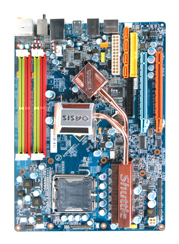
Hotspot information for Shuttle XPC Barebone SX38P2 Pro
Product views with descriptions
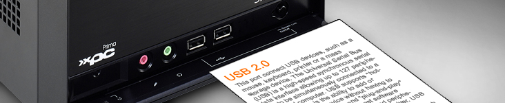
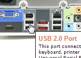
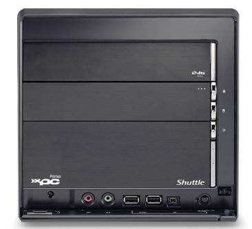
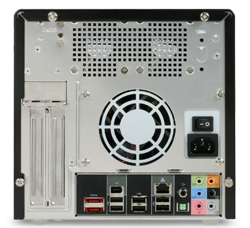
Please move your mouse to the three product images to learn more about connectivity on the front and back panel.
| Frontpanel: |
Backpanel: |
|
|
|
| Mainboard: |
|
|
| |
|
|
| |
|
 |
|
|
|
|
|
|
|
| Cercare |
|
|
|
|
|
|
| Informazione collegata |
|
|
|
|
| Shuttle Newsletter |
|
|
|
|
|
Learn more about the Shuttle D 1416S |
|
|
|
|
 |
| La newsletter di Shuttle, inviata su richiesta, presenta le novità dal mondo Shuttle. | |
|
|
|
|