 |
|
|
|
|
|
|
|
Hotspot information for Shuttle Barebone X27
Product views with descriptions
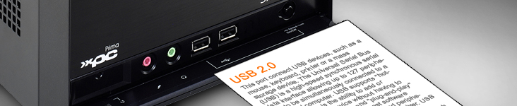
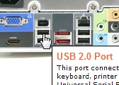
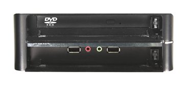
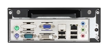
Please move your mouse to the three product images to learn more about connectivity on the front and back panel.
| Frontpanel: |
Backpanel: |
|
|
|
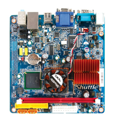
| Mainboard: |
|
|
| |
|
|
| |
|
 |
|
|
|
|
|
|
|
| Cercare |
|
|
|
|
|
|
| Informazione collegata |
|
|
|
|
| Shuttle Newsletter |
|
|
|
|
|
Shuttle Movies |
|

In questa zona potrete scoprire ancora più su Shuttle, attraverso animazioni 3D e filmini.
 | |
|
|
 |
| La newsletter di Shuttle, inviata su richiesta, presenta le novità dal mondo Shuttle. | |
|
|
|
|