 |
 |
 |
|
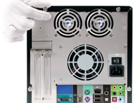
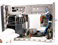
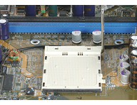
(1) Unscrew the three thumbscrews. |
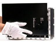
(2) Slide the cover backwards then lift to remove. |
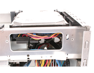
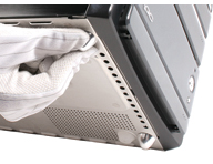
(3) Unplug the Card Reader signal cable. |
|
 |
 |
 |
|
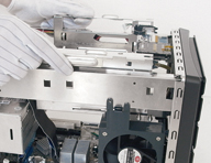
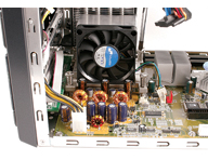
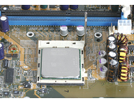
(4) Unbuckle the rack clips. Lift to remove. |
(5) Remove the fan duct |
(6) Disconnect the fan power cable. Unscrew the ICE heat-pipe module and remove. |
|
 |
 |
 |
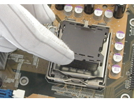
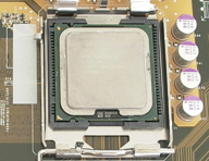
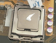
| (7a) Pentium 4 installation. Unlock and raise the socket lever. Remove the protective cover. |
(8a) Align the CPU according to the above diagram. Close the cover and lock with lever. |
(7b) AMD Athlon 64 installation. Raise the socket lever to 90°. |
|
 |
 |
 |
| (8b) Align the CPU according to the above diagram. Gently insert. Return the lever to the horizontal. |
(9) Apply an even layer of thermal paste to the surface of the CPU. |
(10) Install the ICE module. Refasten the screws. Attach the cables (header 1). Replace the fan duct. |
|
 |
 |
 |
|
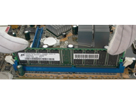
(11) Install DDR. Open the DIMM latches. Align the RAM and insert vertically. Close latches. |
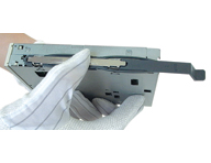
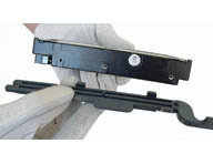
(12) Floppy drive installation (optional). Attach the toolless brackets to the FDD as shown. |
(13) Slide the floppy drive into the rack mount. |
|
 |
 |
 |
|
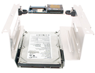
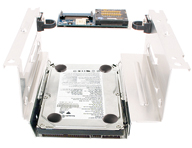
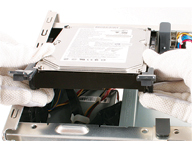
(14) Alternatively, you can install a hard drive in this position. Place in rack and press firmly to lock. |
(15) Attach the 4 dampers on top of the installed drive and press firmly. |
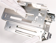
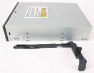
(16) Optical drive installation. Attach the toolless brackets to the optical drive as shown. |
|
 |
 |
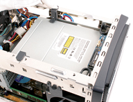 |
| (17) Slide the optical drive into the rack mount. |
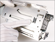
(18) Align the drive optical eject button. You may need to swap the "control rod". |
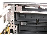
(19) Insert the rack mount into the chassis. Lock in position. Attach card reader cable. |
|
 |
 |
 |
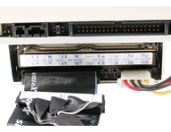
| (20) Attach drives signal and power cables. Attach signal cables to the motherboard. |
(21) Install SATA drives. Attach the toolless brackets as shown above |
(22) Insert the hard drive into the chassis. Lock latches to secure. Repeat as appropriate. |
|
 |
 |
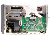 |
| (23) Attach the hard drive signal and power cables. |
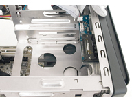
(24) Install expansion card. Unscrew the back panel expansion slot bracket. |
(25) Install expansion card and secure bracket. |
|
 |
 |
 |
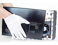
| (26) Close the cover and refasten the screws. |
(27) Attach the front feet to the base of the chassis. |
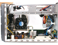
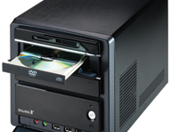
(28) Finished! |