 |
 |
 |
|
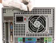
(1) Unscrew the three thumbscrews. |
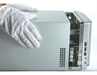
(2) Slide the cover backwards then lift to remove. |
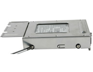
(3) Unfasten the HD rack mount screws and remove. |
|
 |
 |
 |
|
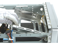
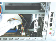
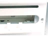
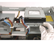
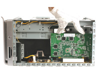
(4) Unfasten the optical drive rack mount screws. Slide the rack backwards, then lift it out of the case. |
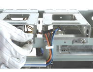
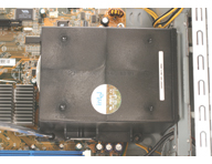
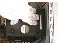
(5) Disconnect the fan power cable. |
(6) Unscrew the thermal module and remove. |
|
 |
 |
 |
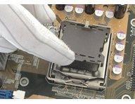
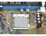
| (7a) Pentium 4 installation. Unlock and raise the socket lever. Remove the protective cover. |
(8a) Align the CPU according to the above diagram. Close the cover and lock with lever. |
(7b) AMD Athlon 64 installation. Raise the socket lever to 90°. |
|
 |
 |
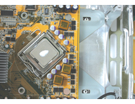 |
| (8b) Align the CPU according to the above diagram. Gently insert. Return the lever to the horizontal. |
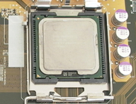
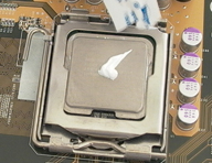
(9) Apply an even layer of thermal paste to the surface of the CPU. |
(10) Place the thermal module on top of the CPU die. |
|
 |
 |
 |
|
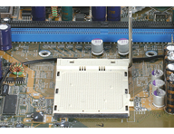
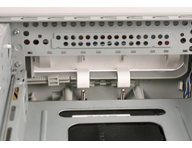
(11) Fasten the thermal module’s screws. |
(12) Connect the fan power cable to header 1. |
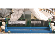
(13) Install DDR. Open the DIMM latches. Align the RAM and insert vertically. Close latches. |
|
 |
 |
 |
|
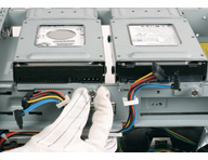
(14) Place the optical drive in the rack. Fasten the four side screws. |
(15) Slide the optical drive into the chassis. |
(16) Open the drive door. Check the alignment of the eject button with the eject mechanism. |
|
 |
 |
 |
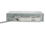
| (17) Press the eject button to check. If poorly aligned, adjust the control rod to suit. |
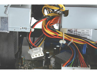
(18) Plug the optical drive and power cable into the optical drive. Refasten screws. |
(19) Place the HDD in the rack and secure with screws from the side. Repeat as appropriate. |
|
 |
 |
 |
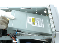
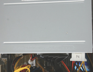
| (20) Place the rack back in the chassis. Refasten screws. |
(21) Connect the IDE/Serial ATA cable and power connector to the HDD. |
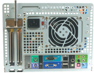
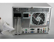
(22) Install expansion card. Unscrew the back panel expansion slot bracket. |
|
 |
 |
 |
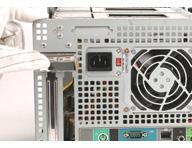
| (23) Lift and remove the PEG/PCI back panel bracket and put the bracket aside. |
(24) Install expansion card and secure bracket. |
(25) If applicable connect the 4 pin power connector to the PCI Express Graphics Card |
|
 |
 |
 |
| (26) Close the cover. |
(27) Refasten the screws. |
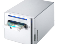
(28) Finished! |