|
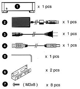
Package Contents
|
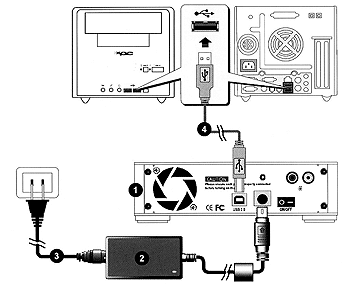
Connection Illustration
|
| |
|
|
How to install an Optical Drive?

|

|
|
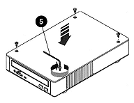
Step 1: Loosen the four top screws and open the cover |
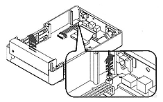
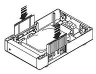
Step 2: Lift out the heat sinks on both sides. |
 |
 |
| Step 3: Remove the front panel and LED cable. |
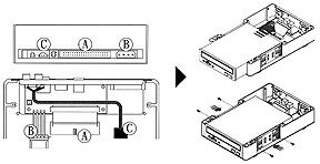
Step 4: Insert the IDE module into the casing.
Connect the power, signal and audio cables as shown.
Secure the module to the casing using four M3x8 screws. |
 |
 |
| Step 5: Re-insert heat sinks on both sides. |
Step 6: Re-attach the top cover. |
|
How to install a Hard Drive Disk?

|
 |
| Step 1: Loosen the four top screws and open the cover |
Step 2: Lift out the heat sinks on both sides. |
 |
 |
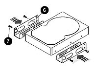
| Step 3: Attach the Hard Drive brackets as shown. |
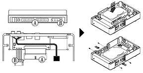
Step 4: Insert the IDE module into the casing.
Connect the power and signal cables as shown.
Secure the module to the casing using four M3x8 screws. |
 |
 |
| Step 5: Re-insert heat sinks on both sides. |
Step 6: Re-attach the top cover. |