Bienvenido al mundo de los mini PC de ShuttlePorqué XPCProductosAplicacionesxCommunityFuentes comercialesSoporteÁrea BusinessPrensa
Sistemas Completos|Barebones|XPC Accessories|Nuestros productos|Noticias sobre productos|Productos Descatalogados|
Products |
Hotspot information for Shuttle XPC Barebone SX38P2 Pro

Hotspot information for Shuttle XPC Barebone SX38P2 Pro

Product views with descriptions

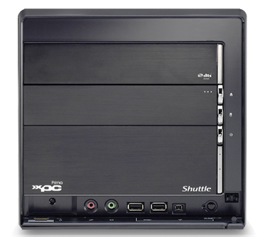
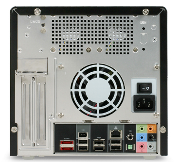
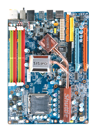
Please move your mouse to the three product images to learn more about connectivity on the front and back panel.

Frontpanel: Backpanel:

Reset Button

Pressing the reset button is the last resort for dealing with a non-responsive computer. The reset button sends a reset signal to all peripherals. It clears the memory and reboots the PC forcibly. Any work not saved to disk will be lost when the reset button is pressed.

Harddisk LED

This LED blinks during hard drive disk read and write activity.

3.5" drive bay

The 3.5" drive bay can be used for a multi-format card reader or floppy disk drive (FDD).

Optical drive bay

This 5.25" bay is normally used for a DVD writer.

Eject Button

If your computer comes with an optical drive, you can use this eject button to eject the disk tray.

Microphone Port

This 1/8 inch (3.5 mm) female connector in pink color can be used to attach a microphone. There are two audio ports (microphone and headphone) located on the front panel which can be used for a head-set. To test a microphone you can use the Windows Sound Recorder application.

Head Phone Port

This 1/8 inch (3.5 mm) female stereo connector in lime color can be used to attach a headphone or headset with an impedance of at least 32 ohms. This connector can also be used as a line-out to connect amplified PC speakers.

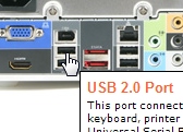
USB 2.0 Port

This port connect USB devices, such as a mouse, keyboard, printer or a mass storage device. The Universal Serial Bus (USB) is a high-speed synchronous serial data interface allowing up to 127 peripherals to be simultaneously connected to a personal computer. USB supports "hot-swap" which is the ability to add or remove a new device without having to reboot the computer and "plug-and-play" operation, in which the host software automatically detects attached peripherals and loads the appropriate driver. USB 2.0 runs at up to 480 Mbit/s and is downward compatible with USB 1.1 which runs up to 12 Mbit/s.

1394 Firewire Port

This is an interface similar to USB, although it’s not as widely used on the PC as it is on Macintosh computers. Its official name is IEEE1394a, but it’s also known as iLink thanks to Sony branding. The speed of 1394a Firewire is 400Mbits/sec (around 50Mbyte/sec). It’s most commonly used with a DV camcorder to transfer digital video to your PC for editing. Other peripherals available with a Firewire interface include external hard drives, external optical drives, scanners and web cameras. The main advantage of Firewire over USB 2.0 is that the bandwidth is not shared between devices. Firewire can also provide more power to an external device than USB. The 6 pin connector differs from the 4 pin (mini) connector by also being able to transfer power to an external device, but it has the same transfer speed and specification as the four wire cable.

Fingerprint Sensor

With an added a layer of security protection thru the integrated biometric fingerprint reader, you can keep your digital identity and data more secure and no longer worry about having to memorize for memorizing multiple passwords.

USB/ Speed-Link Connector

This USB connector can be activated for the Speed-Link-Technology by pressing the Speed-Link-Button. File sharing among two PCs has never been easier with the innovative Speed-Link technology, simply connects both systems thru a simple USB cable (type A-to-A) without having the hassle of driver installation or worry about insufficient space of a DVD disc.

Speed-Link Button

By pressing this button you can activate the Speed-Link mode for one of the front panel USB connectors. File sharing among two PCs has never been easier with the innovative Speed-Link technology, simply connects both systems thru a simple USB cable (type A-to-A) without having the hassle of driver installation or worry about insufficient space of a DVD disc.

Power Button with LED (Power On/Off)

Press the power button to turn on the computer. To avoid losing data, turn off your computer by performing a soft shutdown by the operating system rather than by pressing the power button. If the computer stops responding, press and hold the power button until the computer turns off completely which may take several seconds. You can also use the power button to enter or resume from standby/suspend mode. This button also integrates the power LED, which lights when the computer is turned on.

Power Connector

To this inlet you can attach the mains cord to the power supply. The other end of the cord has a suitable power plug for the locality in which the appliance is used.

Power Supply

This PC has a stable switched-mode power supply with small dimension and high efficency. Power supplies are the devices that power computers. They convert AC power from electric utilities into DC power used in most electronics.

Thumbscrews

This case features toolless entry thanks to the thumbscrews, making it that much easier to get inside without using a screwdriver. Just unscrew the thumbscrews on the back of the chassis cover and slide the cover backwards and upwards. Note: For safety reasons, please ensure that the power cord is disconnected before opening the case.

PCI Express Graphics slot (PEG)

This is a PCI Express Graphics slot (PEG) which is exclusively dedicated for graphics cards with PCI Express x16 (PCIe x16) interface. With 16 serial connections (lanes) it archieves a maximum data transfer rate of up to 4 GB/s in each direction. Its predecessor AGP only supports 2 GB/s and the PCI bus 133 MB/s.

Network Connector (RJ45)

This RJ45 Ethernet port connects the PC directly to a central connecting device, be it hub, switch, or router. Hubs are the least expensive option and simply have multiple RJ45 ports to connect several computers. A switch works similar, but analyzes the data which results in a smoother and more efficient transfer of data. While hubs and switches connect devices to form a Local area network (LAN), routers are used to connect to another network, e.g. the Internet. The two lights next to the connector indicate status and activity for wired network connections. The integrated network controller supports at least Fast Ethernet (10/100 Mbit/s) or even Gigabit Ethernet (GbE, 10/100/1000 Mbit/s).

8 Channel Audio Line Out Ports

Four 1/8 inch (3.5 mm) female stereo jacks to connect analog output devices like amplifiers or amplified speakers with up to 8 audio channels. For a full 7.1 configuration with 7 speakers and 1 subwoofer you need four stereo-mini-to-stereo-RCA cables which are used for (1) front right/left, (2) surround front right/left, (3) sourround back right/left and (4) center/subwoofer.

Audio Line In Port

This 1/8 inch (3.5 mm) female stereo connector in light-blue color can be used as an input to record/digitize analogue audio from external sources such as a CD/tape player, amplifier, television etc.

USB 2.0 Port

This port connect USB devices, such as a mouse, keyboard, printer or a mass storage device. The Universal Serial Bus (USB) is a high-speed synchronous serial data interface allowing up to 127 peripherals to be simultaneously connected to a personal computer. USB supports "hot-swap" which is the ability to add or remove a new device without having to reboot the computer and "plug-and-play" operation, in which the host software automatically detects attached peripherals and loads the appropriate driver. USB 2.0 runs at up to 480 Mbit/s and is downward compatible with USB 1.1 which runs up to 12 Mbit/s.

External Serial ATA connector

You can attach an external SATA mass storage device to the External Serial ATA (eSATA) port, if your device has the appropriate cable and connector. Today, external drives are usually connected via USB or Firewire, which provide less effective bandwidth due to the required bridge and protokol overhead. Standardized in mid-2004, eSATA will likely co-exist alongside USB and Firewire.

Clear CMOS Button

The Clear CMOS Button button allows users to reset BIOS information to factory default settings. To perform the Clear CMOS procedure, first power down the PC and remove the power cord. Then press the Clear CMOS Button by inserting a pointed object (e.g. a pen nib) into the clear CMOS hole. Keep it pressed for 5 seconds. Finally reconnect the power cord and turn on the computer.

Thumbscrews

This case features toolless entry thanks to the thumbscrews, making it that much easier to get inside without using a screwdriver. Just unscrew the thumbscrews on the back of the chassis cover and slide the cover backwards and upwards. Note: For safety reasons, please ensure that the power cord is disconnected before opening the case.

Microphone Port

This 1/8 inch (3.5 mm) female connector in pink color can be used to attach a microphone. There are two audio ports (microphone and headphone) located on the front panel which can be used for a head-set. To test a microphone you can use the Windows Sound Recorder application.

Optical S/PDIF Output (DDL/DTS)

This is an optical S/PDIF Output (also known as TOSlink or Fiber SPDIF). S/PDIF (Sony/Philips Digital Interface Format) is a specifications for carrying digital audio signals in either optical or electrical form - they both give you exactly the same result, only the cable types differ. The ordinary, uncompressed signal only carries a stereo signal.
The integrated audio solution supports the Dolby Digital Live! and DTS connect real-time encoding technologies, which convert any stereo or multichannel audio signal into a Dolby Digital or DTS bitstream and transports it via a single S/PDIF cable to an A/V receiver / home theater system for playback. Dolby Digital Live! and DTS connect turn your PC into an action-packed entertainment experience that surrounds you in sound.

Electrical S/PDIF Output (DDL/DTS)

This is an electrical S/PDIF Output (RCA jack for coaxial cable). S/PDIF (Sony/Philips Digital Interface Format) is a specifications for carrying digital audio signals in either optical or electrical form - they both give you exactly the same result, only the cable types differ. The ordinary, uncompressed signal only carries a stereo signal.
The integrated audio solution supports the Dolby Digital Live! and DTS connect real-time encoding technologies, which convert any stereo or multichannel audio signal into a Dolby Digital or DTS bitstream and transports it via a single S/PDIF cable to an A/V receiver / home theater system for playback. Dolby Digital Live! and DTS connect turn your PC into an action-packed entertainment experience that surrounds you in sound.

Power Supply Switch

The power button at the front panel can only turn the PC into a standby/suspend power saving mode, where a standby power is supplied to specific devices that may be involved in waking the computer. In this mode, the computer continues to draw a small amount of power, often without performing a useful purpose. This can be avoided by unplugging the power cable or using the hard-off switch at the back panel.

Two 60mm fans

The two 60mm fans at the top rear of the chassis run in tandem protected by grills on both sides. Their primary purpose is to pull heat from the top of the case where up to two Serial-ATA hard drives can be mounted.

Wireless LAN (optional)

This is a perforation for the antenna of an optional Wireless LAN module (Shuttle XPC Accessory PN20) which supports up to 54 Mbps transfer rate according to 802.11g standard. The WLAN module is connected to an internal USB port. You can connect to the Internet when in proximity of an access point or you can use the Ad-hoc mode for client to client connections. To ensure WLAN security, it also provides strong WPA encryption and firewall, to protect the data from WLAN. You should not use the weak WEP encryption protocol.

1394 Firewire Port

This is an interface similar to USB, although it’s not as widely used on the PC as it is on Macintosh computers. Its official name is IEEE1394a, but it’s also known as iLink thanks to Sony branding. The speed of 1394a Firewire is 400Mbits/sec (around 50Mbyte/sec). It’s most commonly used with a DV camcorder to transfer digital video to your PC for editing. Other peripherals available with a Firewire interface include external hard drives, external optical drives, scanners and web cameras. The main advantage of Firewire over USB 2.0 is that the bandwidth is not shared between devices. Firewire can also provide more power to an external device than USB. The 6 pin connector differs from the 4 pin (mini) connector by also being able to transfer power to an external device, but it has the same transfer speed and specification as the four wire cable.

Mainboard:

Back Panel Connectors

The Back Panel is an electrical panel consisting of several connectors for external peripherals. Common ports are audio, network, usb and firewire. When the mainboard chipset integrates a video controller you will also find at least one video port. On newer PCs you may also find an external Serial ATA port, but at the same time you may miss some of the older (legacy) ports: PS/2 for mouse and keyboard, serial, parallel.

PCI Express Graphics slot (PEG)

This is a PCI Express Graphics slot (PEG) which is exclusively dedicated for graphics cards with PCI Express x16 (PCIe x16) interface. With 16 serial connections (lanes) it archieves a maximum data transfer rate of up to 4 GB/s in each direction. Its predecessor AGP only supports 2 GB/s and the PCI bus 133 MB/s.

Processor Socket 775 (Intel)

Intel's processor socket 775, introduced in June 2004, is also called Socket T or LGA 775 and is Intel's latest CPU socket for desktop processors. LGA stands for Land Grid Array, which means that the pins are on the motherboard, not the processor. In July 2006, Intel released the Core 2 Duo processor for socket 775 (codenamed Conroe), which offers a higher level of computing performance with lower clock speeds, and lower power consumption. To check the compatibility of a particular processor in connection with this mainboard please refer to the compatibility lists at Shuttle's website.

Battery

This is a conventional coin-shaped non-rechargeable 3 volt lithium cell. This is a battery, which powers the CMOS memory that holds configuration information, and the internal date-and-time clock (RTC).

Southbridge (Chipset)

The chipset of this mainboard consists of two components: the Northbridge (NB) and the Southbridge (SB). The Southbridge is a chip that implements the "slower" capabilities of the mainboard and is not directly connected to the CPU. A particular southbridge will usually work with several different northbridges, but these two chips must be designed to work together. A typical Southbridge includes functions for power management, interrupt controller, USB and may include interfaces to the following components: mass storage drives (PATA/SATA), PCI/PCIe x1 bus, BIOS EEPROM, I/O controller (serial, parallel, PS/2 mouse/keyboard, floppy drive), audio codec chip, network controller and more.

DDR2 Memory Slots

These are 240-pin DIMM sockets to install DDR2 SDRAM memory modules used for high speed storage of the working data of a computer. Its primary benefit of DDR2 over its predecessor DDR is its higher bus speed and lower power consumption. The amount of RAM you have determines how many programs can be executed at one time and how much data can be handled without swapping data to a hard disk. Upgrading your memory is one of the most cost effective ways to boost your system performance.
Windows
Version
Minimum Recommended
Minimum
3D Gaming,
Graphics/Vid.
Maximum
95/98/ME 128 MB 256 MB 512 MB 512 MB
2000/XP 256 MB 512 MB 1 GB 4 GB *)
Vista 512 MB 1 GB 2 GB 8 GB **)
*) only approx. 3.5 GB available **) only with P2 series Shuttle XPC's (4 memory sockets) and 64 bit operating system

Serial ATA Header

Serial ATA (SATA) is the successor to the legacy Parallel ATA (PATA or ATA) and mainly used to connect hard disks and optical drives to the mainboard.
Parallel ATA Serial ATA
Data cable
(wires, max. length)
40 pin connector
80 pin ribbon cable
max. 46 cm
4 wires (2x serial unidirectional)
more compact, better airflow
max. 100 cm (external: 200 cm)
Max. data rate 100 or 133 MB/s 150 or 300 MB/s
(1.5 or 3.0 Gbit/s)
Devices per channel 2 1
Optional features
Innovations
- Native command queuing (NCQ)
Hot-swapping
External connector (eSATA)

Power Supply Connector

The ATX V1.x specification defines a 20 pin main power connector which provides 3.3V, 5V, 12V and 5V standby lines to the mainboard. The power-on wire allows to turn the PSU off by software. ATX V2.x standard defines a new 24 pin connector to support 75W PCI-Express requirements, but most mainboards still use the old 20 pin connector in combination with an additional 4 pin ATX12V (12V), or combine 8 pin ATX12V with 6 pin AUX (3.3V and 5V).

Parallel ATA Header

This is the 40-pin Parallel ATA (IDE) onboard header for hard disks or optical drives. One connector supports up to 2 devices. The appropriate ribbon cables have one connector for the mainboard (at one end) and one or two for device attachment (master and/or slave device). According to the latest standards 80 wires are required for the ribbon cable in order support the higher transfer speeds (66MB/s or higher) - the additional 40 pins being dedicated to ground reducing crosstalk. With the introduction of Serial ATA in 2003, the original ATA was renamed Parallel ATA (PATA). It is expected that SATA will replace the older technology.

Connector for the front panel

The is a special flat cable connector for the front panel. It carries signal for the buttons (power and reset) and LEDs (power and HDD).

Voltage Regulator for the processor

The voltage regulator circuit is soldered to the mainboard and provides a processor the appropriate supply voltage. This device can auto-detect the required supply voltage from the processor.

BIOS EEPROM

The BIOS EEPROM is a memory chip which is mounted in a socket on the mainboard, so it is removable. It stores the BIOS (Basic Input/Output System) which is a small program that stores configuration details about your computer hardware and enables your computer to boot up. Every time your computer is switched on, the BIOS loads configuration data into main memory, performs a routine diagnostic test on your hardware, then loads the operating system. You can enter a simple BIOS setup program by pressing the DEL key shortly after the machine starts to boot. This is an interface where the user can configure items such as time, date, boot settings, hard drive details, etc. The system configuration data is stored in the battery buffered CMOS memory which is not inside the BIOS EEPROM. By using the "Clear CMOS" jumper you can reset the CMOS data to factory default settings, if necessary. The EEPROM retains the data even when power is turned off and it can be reprogrammed using a Flash Utility. This allows a convenient way to upgrade your BIOS as newer features are released, however, the risk is that an improperly executed or aborted BIOS update can render the computer or device unusable. Shuttle is not liable for any damage or loss of data caused by the BIOS update.

Input/Output Controller

The Input/Output controller is a single chip that typically controls the slower-speed standardized peripherals common to most personal computers. These functions include for example serial port control, parallel port control and FDD control.

Onboard Audio Input

This is an onboard header which provides an analog audio input for an auxiliary (AUX) device or the internal optical drive.

Audio CODEC

In the late 1990s, many computer manufacturers began to replace plug-in soundcards with a "AC'97 audio codec", usually a small square chip with 48 pins. The word "Audio Codec" refers to the analog component of the architecture, a combined audio AD/DA-converter - it encodes/decodes signals to/from analog audio from/to digital audio. This should not be confused with a software codec in the sense of converting from one binary format to another, such as an MP3 codec. The digital part is integrated into the mainboards chipset. In 2004 AC'97 was superseded by Intel High Definition Audio (HD Audio) with PCI-Express x1 Interface, which supports eight channels at 192 kHz/32-bit quality, while the AC‘97 specification with a serial (AIC or I2S) interface can only support six channels at 48 kHz/20-bit.

Floppy Disk Drive Header

This is the 34-pin header/connector for a floppy disk drive (FDD). With the arrival of mass Internet access, cheap Ethernet and USB flash drives, the floppy was no longer necessary for data transfer either, and the floppy disk was essentially superseded. The FDD might still be required if you want to install RAID drivers in memory prior to installing Windows XP.

Power Supply Connector

The ATX V1.x specification defines a 20 pin main power connector which provides 3.3V, 5V, 12V and 5V standby lines to the mainboard. The power-on wire allows to turn the PSU off by software. ATX V2.x standard defines a new 24 pin connector to support 75W PCI-Express requirements, but most mainboards still use the old 20 pin connector in combination with an additional 4 pin ATX12V (12V), or combine 8 pin ATX12V with 6 pin AUX (3.3V and 5V).

Fan Connector

Basically, there are two kind of onboard headers for cooling fans: 3 pin (RPM controlled) and 4 pin (PWM controlled). 2 wires are required to power the fan (12V). The third wire is a RPM output signal (also tach or sensor) to determine the rotation rate: it pulses twice, for every full rotation of the fan blade. A hardware monitor circuit on the mainboard can use this signal to adjust the fan speed according to CPU temperature by voltage control: the voltage is reduced or increased to speed or slow the fan. The optional 4th wire is a Pulse Width Modulation (PWM) input, which is square wave signal at 25kHz - above human hearing. The pulse width of the PWM signal indicates the desired speed. A 50% wide signal might indicate half speed. A 75% wide pulse in PWM might mean three quarters speed and so on. This is different from voltage control. Online vendors make this a bit more confusing by often refering to a 3 pin fan to 4 pin power adapter cable - which usually means that two wires coming from the 4 pin Molex connector to a 3 pin fan, but the RPM wire is not assigned.

Northbridge (Chipset)

The chipset of this mainboard consists of two components: the Northbridge (NB) and the Southbridge (SB). The Northbridge is the faster of the two and handles the data flows to CPU, DRAM memory, graphics card and Southbridge chip. Special bus systems are uses for the communication, e.g. Front Side Bus for Intel CPUs, Memory Bus for DRAM memory modules, PCI Express for the graphics and the Chipset Interconnect bus between NB and SB. The performance of these connections depends on the clock speed, the data-width and the latency (or 'access' time). Some northbridges also contain an integrated video controller. The northbridge on a particular system's mainboard is the most prominent factor in dictating the number, speed, and type of CPU and the amount, speed, and type of DRAM that can be used (please refer to the specification of this product).

Fan Connector

Basically, there are two kind of onboard headers for cooling fans: 3 pin (RPM controlled) and 4 pin (PWM controlled). 2 wires are required to power the fan (12V). The third wire is a RPM output signal (also tach or sensor) to determine the rotation rate: it pulses twice, for every full rotation of the fan blade. A hardware monitor circuit on the mainboard can use this signal to adjust the fan speed according to CPU temperature by voltage control: the voltage is reduced or increased to speed or slow the fan. The optional 4th wire is a Pulse Width Modulation (PWM) input, which is square wave signal at 25kHz - above human hearing. The pulse width of the PWM signal indicates the desired speed. A 50% wide signal might indicate half speed. A 75% wide pulse in PWM might mean three quarters speed and so on. This is different from voltage control. Online vendors make this a bit more confusing by often refering to a 3 pin fan to 4 pin power adapter cable - which usually means that two wires coming from the 4 pin Molex connector to a 3 pin fan, but the RPM wire is not assigned.

Onboard USB Connector

This is an onboard USB header with 1x5 pins (or 2x5 pins) which provide one (or two) USB interfaces you want to install additional internal components, such as a 3.5" card reader or a Shuttle Wireless-LAN module.

Onboard USB Connector

This is an onboard USB header with 1x5 pins (or 2x5 pins) which provide one (or two) USB interfaces you want to install additional internal components, such as a 3.5" card reader or a Shuttle Wireless-LAN module.

Header for PS/2 keyboard/mouse

This onboard header can be used for a PS/2 adapter to connect a keyboard and mouse with PS/2 ports. Today, these input devices are usually equipped with a USB connector, therefore Shuttle deletes the PS/2 connectors in the back panel in favor of other ports.

Solid capacitors

The new generation of "solid capacitors" guaranteed to deliver maximum stability, reliability and longer system lifetime for the ultimate PC gaming and entertainment experience.

Solid capacitors

The new generation of "solid capacitors" guaranteed to deliver maximum stability, reliability and longer system lifetime for the ultimate PC gaming and entertainment experience.

Connector for the front panel

The is a special flat cable connector for the front panel. It carries signal for the buttons (power and reset) and LEDs (power and HDD).

CIR Infra Red port

The Consumer Infra Red (CIR) port can be used to connect an IR diode for medium-range (10m) InfraRed control of "consumer" devices, such as HI-FI sets, TV boxes, etc. On other mainboards you may find a traditional IrDA interface which only supports ranges of typically less than 2m.

PCI Express Graphics slot (PEG)

This is a PCI Express Graphics slot (PEG) which is exclusively dedicated for graphics cards with PCI Express x16 (PCIe x16) interface. With 16 serial connections (lanes) it archieves a maximum data transfer rate of up to 4 GB/s in each direction. Its predecessor AGP only supports 2 GB/s and the PCI bus 133 MB/s.

Ethernet Network Controller

Ethernet is a family of networking technologies for local area networks (LANs), standardized as IEEE 802.3. You can find the network controller on a Network interface card (NICs) or integrated as a LAN-on-Motherboard (LOM) solution. In traditional PC architecture, the network controller is attached to the PCI or PCI-Express bus. Today, most board-mounted network chips only includes the PHysical Layer (PHY) transceiver, whereas the other logical part of the controller, the Media Access Controller (MAC), is integrated into the southbridge of the mainboards chipset. Each Ethernet station is given a single 48-bit MAC address, which is used both to specify the destination and the source of each data packet.

OASIS heat pipe cooling system

The newly designed OASIS cooling technology deliver a unique system of heat-sinks based on heat pipe technology. It covers the MOSFETs of the voltage regulator and the north and south bridge of the chipset. Advantages: it works fanless (that means noiseless) and it leads to additional system stability and longer component lifetime through lower temperatures.

Solid capacitors

The new generation of "solid capacitors" guaranteed to deliver maximum stability, reliability and longer system lifetime for the ultimate PC gaming and entertainment experience.

Solid capacitors

The new generation of "solid capacitors" guaranteed to deliver maximum stability, reliability and longer system lifetime for the ultimate PC gaming and entertainment experience.

back previous article send print
top
Búsqueda
Información adicional
Shuttle Newsletter

Shuttle StoreLocator


El boletín informativo de Shuttle le informa sobre todas las novedades en torno a Shuttle.
2009
17.10.2009 02:05:57