 |
 |
 |
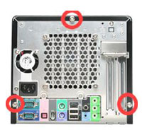
(1) Unfasten the screws on the back panel and remove the case.
|
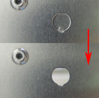
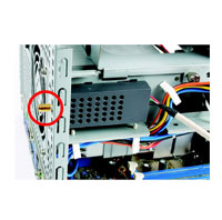
(2) Use a 6mm screwdriver to puncture the perforated hole on the back panel from the outside in. Once the screwdriver can pass through the hole, carefully snap the metal tag off.
Note: If the cover still does not detach, carefully bend it by pushing down from the inside of the chassis. |
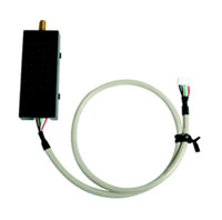
(3) Take out the XPC 802.11b/g Wireless Kit.
Note : The installation process of XPC 802.11b/g Wireless Kit will be different for each XPC model and dependent on each XPC
design. Please refer to the following installation instructions for your XPC model. |
|
| For P-Series: |
 |
 |
 |
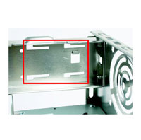
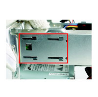
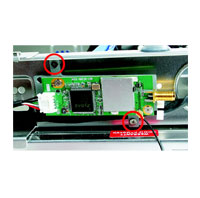
| (4.1) Install the XPC 802.11b/g Wireless Kit to the four attachment points as shown below. |
|
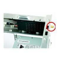
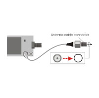
(4.2) Install the antenna cable connector through the side reserve hole into the back chassis.
Caution: When inserting the cable connector, check the socket alignment and only push horizontally. Do not turn or twist the cable.
Note: If some difficulty is found while inserting the antenna socket into the reserve hole, make sure the surface is clean. Finally, check the alignment and then use some more force.
Refer to Step5. |
|
| For i-Series: |
 |
 |
 |
| (4.1) Install the XPC 802.11b/g Wireless Kit to the four attachment points as shown below. |
|
(4.2) Install the antenna cable connector through the side reserve hole into the back chassis.
Caution: When inserting the cable connector, check the socket alignment and only push
horizontally. Do not turn or twist the cable.
Note: If some difficulty is found while inserting the antenna socket into the reserve hole, make
sure the surface is clean. Finally, check the alignment and then use some more force.
Refer to Step5 |
|
| For G,G2,G4,G5,L -Series: |
 |
 |
 |
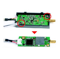
| (4.1) Unscrew the two XPC 802.11b/g Wireless Kit’s screws and remove the module cover. |
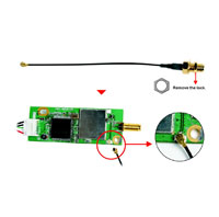
(4.2) Take out the Antenna cable connector and remove the lock, then install it to the XPC 802.11b/g Wireless Kit. |
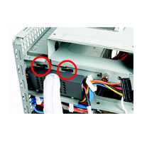
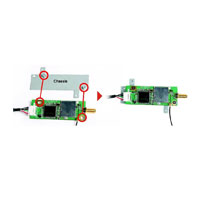
(4.3) Take out the chassis and fasten the XPC 802.11b/g Wireless Kit to the chassis with the two screws. |
 |
 |
 |
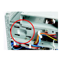
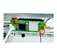
| (4.4) Screw the XPC 802.11b/g Wireless Kit to the two holes on the upside of the chassis arm, near the rear of the XPC. |
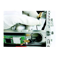
(4.5) Install the antenna cable connector through the side reserve hole into the back chassis. |
Caution: When inserting the cable connector, check the socket alignment and only push horizontally. Do not turn or twist the cable.
Note: If some difficulty is found while inserting the antenna socket into the reserve hole, make sure the surface is clean. Finally, check the alignment and then use some more force. |
 |
|
|
|
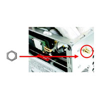
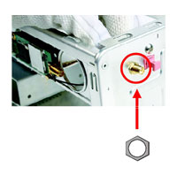
(4.6) Use a lock to secure the antenna from the outside.
Refer to Step5. |
|
|
|
| For K-Series: |
|
|
 |
| (4.1) Unscrew the two XPC 802.11b/g Wireless Kit’s screws and remove the module cover. |
(4.2) Take out the Antenna cable connector and remove the lock, then install it to the XPC 802.11b/g Wireless Kit. |
(4.3) Screw the XPC 802.11b/g Wireless Kit to the two holes on the upside of the chassis arm, near the rear of the XPC. |
|
|
 |
| (4.4) Install the antenna cable connector through the side reserve hole into the back chassis. |
Caution: When inserting the cable connector, check the socket alignment and only push horizontally. Do not turn or twist the cable.
Note: If some difficulty is found while inserting the antenna socket into the reserve hole, make sure the surface is clean. Finally, check the alignment and then use some more force. |
(4.5) Use a lock to secure the antenna from the outside.
Refer to Step5 |
|
| Continue with all XPC series: |
 |
 |
 |
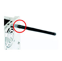
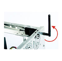
| (5) Screw the antenna onto the exposed thread. Set the antenna to vertical for good reception. |
Note: Make sure all the connectors are aligned in the correct direction. |
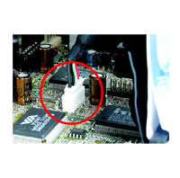
(6) Connect the signal cable from the XPC 802.11b/g Wireless Kit to the 5-pin USB header located on the motherboard. Double check all connections before continuing. |
|
|
|
|
(7) Attach the case and fasten the thumbscrews to complete the hardware installation. |
|
|