 |
 |
 |
|
(1) Unscrew the three thumbscrews. |
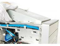
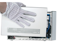
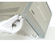
(2) Slide the cover backwards then lift to remove. |
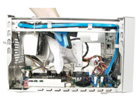
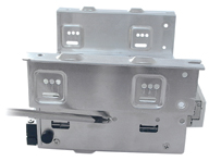
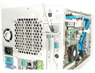
(3) Unfasten the rack mount screws. Slide the rack backwards, then lift it out of the case. |
|
 |
 |
 |
|
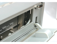
(4) For G serie, unscrew and remove the front bay covers. |
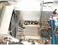
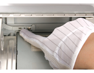
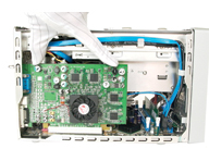
(5) Unfasten the ICE fan thumbscrews on the back of the chassis. |
(6) Disconnect the fan power cable. Unscrew the ICE heat-pipe module and remove. |
|
 |
 |
 |
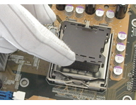
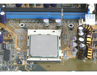
| (7a) Pentium 4 installation. Unlock and raise the socket lever. Remove the protective cover. |
(8a) Align the CPU according to the above diagram. Close the cover and lock with lever. |
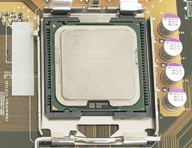
(7b) AMD Athlon 64 installation. Raise the socket lever to 90°. |
|
 |
 |
 |
| (8b) Align the CPU according to the above diagram. Gently insert. Return the lever to the horizontal. |
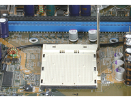
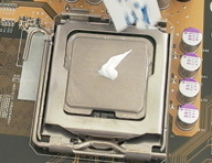
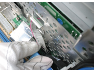
(9) Apply an even layer of thermal paste to the surface of the CPU. |
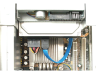
(10) Install the ICE module. Refasten the screws. Attach the cables (header 1). Replace the fan duct. |
|
 |
 |
 |
|
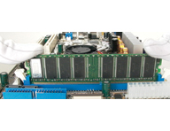
(11) Install DDR. Open the DIMM latches. Align the RAM and insert vertically. Close latches. |
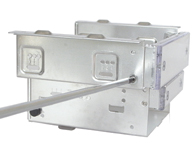
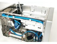
(12) Place HDD(s) in the rack and secure with screws from the side. If applicable, install FDD in appropriate bay. |
(13) Attach cables to the mother board. Place the rack back in the chassis. Refasten screws. |
|
 |
 |
 |
|
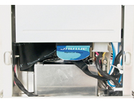
(14) Connect the IDE/SATA cable and power connector to the HDD(s). |
(15) Connect the FDD cable and power connector to the Floppy drive. |
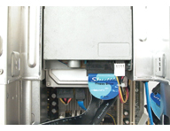
(16) Slide the optical drive into the chassis. |
|
 |
 |
 |
| (17) Open the drive door. Check the alignment of the eject button with the eject mechanism. Press the eject button to check. |
(18) If poorly aligned, adjust the control rod to suit. If successful, jump to step 23. |
(19) You may find that it still does not align. In this case, you will need to change rod as follows: Remove the front panel USB cable. |
|
 |
 |
 |
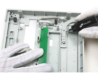
| (20) Unlock the four chips. Remove the front panel. |
(21) Remove the 1.2 mm control rod. Take out the 1.8 mm control rod from the accessory box and insert it in the slot as show. |
(22) Connect the USB cable. Reattach the front panel. Check the alignment and adjust if necessary. |
|
 |
 |
 |
| (23) Fasten the four side screws. Plug the optical drive and power cable into the optical drive. |
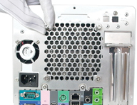
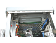
(24) Install expansion card. Unscrew the back panel expansion slot bracket. |
(25) Install expansion card and secure bracket. Connect power connectors as appropriate. |
|
 |
 |
 |
| (26) Close the cover and refasten the screws. |
(27) Attach the front feet to the base of the chassis. |
(28) Finished! |