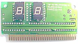
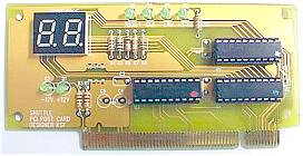
Pfad: Home Award Bios 4.51PG Postcodes
|
| Hex | Name | Description |
| C0 | Turn Off Chipset Cache | OEM Specific-Cache control |
| 1 | ProcessorTest1 | Processor Status (1FLAGS) Verification. Tests the following processor status flags: carry, zero, sign, overflow, The BIOS sets each flag, verifies they are set, then turns each flag off and verifies it is off. |
| 2 | ProcessorTest2 | Read/Write/Verify all CPU registers except SS, SP, and BP with data pattern FF and 00. |
| 3 | Initialize Chips | Disable NMI, PIE, AIE, UEI, SQWV |
| 4 | Test Memory Refresh Toggle | RAM must be periodically refreshed to keep the memory from decaying. This function ensures that the memory refresh function is working properly |
| 5 | Blankvideo, Initialize keyboard | Keyboard controller initialization |
| 6 | Reserved | - |
| 7 | Test CMOS Interface and Battery Status | Verifies CMOS is working correctly, |
| BE | Chipset Default Initialization | Program chipset registers with power on BIOS defaults. |
| C1 | Memory presence test | OEM Specific-Test to size on-board memory |
| C5 | Early Shadow | OEM Specific-Early Shadow enable for fast boot. |
| C6 | Cache presence test | External cache size detection |
| 8 | Setup low memory | Early chip set initialization |
| 9 | Early Cache Initialization | Cyrix CPU initialization |
| A | Setup Interrupt Vector Table | Initialize first 120 interrupt vectors with SPURIOUS_INT_HDLR and initialize INT 00h-1Fh according to INT_TBL |
| B | Test CMOS RAM Checksum | Test CMOS RAM Checksum, if bad, or insert key pressed, load defaults. |
| C | Initialize keyboard | Detect type of keyboard controller (optional) Set NUM_LOCK status. |
| D | Initialize Video Interface | Detect CPU clock. |
| E | Test Video Memory | Test video memory, write sign-on message to screen. |
| F | Test DMA Controller 0 | BIOS checksum test. |
| 10 | Test DMA Controller 1 | - |
| 11 | Test DMA Page Registers | Test DMA Page Registers. |
| 12-13 | Reserved | - |
| 14 | Test Timer Counter 2 | Test 8254 Timer 0 Counter 2. |
| 15 | Test 8259-1 Mask Bits | Verify 8259 Channel 1 masked interrupts by alternately turning off and on the interrupt lines. |
| 16 | Test 8259-2 Mask Bits | Verify 8259 Channel 2 masked Interrupts by alternately turning off and on the interrupt lines. |
| 17 | Test Stuck 8259's Interrupt Bits | Turn off interrupts then verify no interrupt mask register is on. |
| 18 | Test 8259 Interrupt Functionality | Force an interrupt and verify the interrupt occurred. |
| 19 | Test Stuck NMI Bits (Parity/IO Check) | Verify NMI can be cleared. |
| 1A | Display CPU clock | |
| 1B-1E | Reserved | - |
| 1F | Set EISA Mode | If EISA non-volatile memory checksum is good, execute EISA initialization. If not, execute ISA tests an clear EISA mode flag. Test EISA Configuration Memory Integrity (checksum & communication Interface). |
| 20 | Enable Slot 0 | Initialize slot 0 (System Board). |
| 21-2F | Enable Slots 1-15 | Initialize slots 1 through 15. |
| 30 | Size Base and Extended Memory | Size base memory from 256K to 640K |
| 31 | Test Base and Extended Memory | Test base memory from 256K to 640K and extended memory above 1MB using various patterns. |
| 32 | Test EISA Extended Memory | If EISA Mode flag is set then test EISA memory found in slots initialization. NOTE: This test is skipped in ISA mode and can be skipped with ESC key in EISA mode. |
| 33-3B | Reserved | - |
| 3C | Setup Enabled | - |
| 3D | Initialize & Install Mouse | Detect if mouse is present, initialize mouse, install interrupt vectors. |
| 3E | Setup Cache Controller | Initialize cache controller. |
| 3F | Reserved | - |
| BF | Chipset Initialization | Program chipset registers with Setup values |
| 40 | Initialize Floppy Drive & Controller | Initialize floppy disk drive controller and any drives. |
| 42 | Initialize Hard Drive & Controller | initialize hard drive controller and any drives. |
| 43 | Detect & Initialize Serial/Parallel Ports | Initialize any serial and parallel ports (also game port). |
| 44 | Reserved | - |
| 45 | Detect & Initialize Math Coprocessor | Initialize math coprocessor. |
| 46 | Reserved | - |
| 47 | Reserved | - |
| 48-4D | Reserved | - |
| 4E | Manufacturing POST Loop or Display Messages | Reboot if Manufacturing POST Loop pin is set. Otherwise display any messages (i.e., any non-fatal errors that were detected during POST) and enter Setup. |
| 4F | Security Check | Ask password security (optional). |
| 50 | Write CMOS | Write all CMOS values back to RAM and clear screen. |
| 51 | Pre-boot Enable | Enable parity checker |
| 52 | Initialize Option ROMs | Initialize any option ROMs present from C8000h to EFFFFh. NOTE: When FSCAN option is enabled, ROMs initialize from C8000h to F7FFFh. |
| 53 | Initialize Time Value | Initialize time value in 40h: BIOS area. |
| 60 | Setup Virus Protect | Setup virus protect according to Setup |
| 61 | Set Boot Speed | Set system speed for boot |
| 62 | Setup NumLock | Setup NumLock status according to Setup |
| 63 | Boot Attempt | Set low stack Boot via INT 19h. |
| B0 | Spurious | If interrupt occurs in protected mode. |
| B1 | Unclaimed NMI | If unmasked NMI occurs, display |
| E1-EF | Setup Pages | E1- Page 1, E2 - Page 2, etc. |
| FF | Boot | - |
Quelle: http://www.award.com/docs/postcode.htm
![]()
Druck-Version der Originalseite: http://de.shuttle.com/postcode.htm
Shuttle Computer Deutschland - Änderungen und Druckfehler vorbehalten. Datum:
30.4.2008


